2006 The former Hitachi Cable News Release
Information (including product prices, product specifications, details of services, launch dates, inquiry information, and URLs) contained in this news release is current as of the date of the press release but is subject to change without notice. Please note that details may differ from those effective on the search date.
Successful Determination of One Factor in the Suppression of Whisker Formation in Lead-Free Tin-Plated FFC (Flexible Flat Cable)
Here we report on Hitachi Cable's success in suppressing the formation of "whiskers" (hair-like tin crystals) on lead-free tin-plated surfaces for use in flexible flat cables (FFC) by applying nano-order zinc coating; we then describe the mechanism behind this suppression.
FFC is a flat, multicore cable with multiple electrical conductors aligned in parallel and enveloped by insulating film. This conductor can be bent inside an electronic device, and is frequently used in digital cameras, audio equipment, home electronic appliances such as LCD TV sets, and office appliances (Fig. 1).
Conventionally, solder plating using tin-lead alloys has been applied to FFC conductors to prevent problems when attaching them to the relevant connectors. However, with recent developments?including the enforcement of the "Directive 2002/95/EC of the European Parliament and of the Council of 27 January 2003" (RoHS Directive) in July of this year in the European Union (EU), we have been faced with the need to eliminate the use of lead in products.
However, it has been found that the use of tin plating?the most frequently chosen replacement for solder plating in FFC-leads to hair-like formations of tin crystals on tin-plating surfaces near the connection between the FFC and the connector (Fig. 2). These whiskers often trigger malfunctions in electronic devices by causing short-circuits in the FFC wiring.
When tin-plating is applied to FFC conductors in air, an extremely thin tin oxide film is formed on the surface of the tin plating. This film is deformed by the force exerted when the FFC is attached to connectors or the like, and it is theorized that stress is generated and concentrated on the surface of this thin oxide film. It is considered that whisker formation grew in the weak areas of the oxide film surface, where the stress concentrates. The mechanism of whisker formation is not fully understood and awaits further study.
Our group has provided whisker-suppressed tin-plated conductor FFC since the latter half of 2000, and whisker-free gold-plated conductor FFC since the first half of 2005. Furthermore, from the first half of 2004, we have pursued studies on whisker suppression technologies for tin-plated FFC, which is more cost-effective than gold-plated FFC.
Based on the results of various studies, it was found that whisker formation could be efficiently suppressed by applying a thin zinc nano-coating to the surface of the tin plating. Thus, a "modified(II) tin-plated conductor" was developed, in which a nano-order zinc coating is applied to tin-plated surfaces, and we have been mass-producing FFC using this conductor since the latter half of 2005. The product was well received and has been adopted by major electronic appliance companies and connector manufacturers, but the mechanism of whisker suppression still remained to be resolved.
In such circumstances, analysis and investigation of the whisker suppression phenomenon in FFC using modified(II) tin-plated conductors were carried out under the guidance of Professor Emeritus Motohiro Kanno of the University of Tokyo, and we have succeeded in determining one factor which affects the suppression of whisker formation.
Previously we learned that the whisker suppression effect is observed when the zinc coating in the modified(II) tin-plated conductor is extremely thin. We will first describe on this analysis process.
First, samples having variable thickness of the zinc nano-coating layer on the surface of the tin plating were prepared as model cases and the thickness and the elemental composition of the layer were measured, Then examined the effect of whisker suppression. We found that the suppression effect improved with a decrease in thickness of the zinc nano-coating layer, and that the optimum thickness was approximately 3 nanometers.
Next, we prepared prototypes of a modified(II) tin-plated conductor resembling the actual product, attempting to reproduce the optimum thickness and the conditions of the elemental compositions in the model experiment above. A FFC sample was then created using this conductor, and we performed an experiment to evaluate the whisker suppression effect and to confirm the structure of the surface oxide film.
We performed an experiment to evaluate whisker formation by connecting the FFC to connectors using 250 conductors. The states of whisker formation were then observed in detail using a scanning electron microscope and compared. The results showed that whisker formation in the FFC conductors using modified(II) tin-plated conductors having a zinc nano-coating was significantly suppressed (a nearly three-fold suppression) relative to FFC that was tin-plated only.
It was confirmed that the elemental composition and condition of the prototype sample was similar to that of the model experiment, and the presence of zinc, zinc oxide, and tin oxide was confirmed in the approximately 3-nanometer layer of the zinc coating (Figs. 3 & 4). On the other hand, tin oxides (SnO and SnO2) were observed on the surface of the tin plating FFC sample as predicted. (See Fig. 5, showing the model conditions on the surface of the nanometer layer.) These results indicate that the conditions of the surface oxide film on the plating were changed by the application of the zinc nano-coating.
The connection part between the FFC and the connector revealed that the tin plating had been deformed in the stressed region (Fig. 2), and that whisker formation occurred in such regions. It was theorized that the change in the condition of the nano-order film on the surface of the tin plating worked to dissipate and release the stress (driving force) that induces whisker formation in the deformed areas. Therefore, we examined the change in properties near an indentation using the Vickers Hardness Test (see *1), assuming conditions of FFC joint with a connector. After the application of strain which was performed by a mono-axial tensile test (*2) -an extreme-case test we observed surface properties using an electron microscope. As a result of this experiment, we found that the morphology of the film surface is significantly altered in the conductors with zinc nano-coating compared to tin-plating only conditions. With considering these results, we may infer that the whisker suppression effect of the modified(II) tin-plated conductor is due to a reduction of the driving force inducing whisker formation; this reduction is caused by changes in the nano-order film properties.
In this way, we were able to resolve one factor in the suppression mechanism of whisker formation in FFC using modified(II) tin-plated conductors, and we believe our finding has enabled us to approach our goal in providing safer products to our customers. Furthermore, we hope that the results of our present analysis will aid future studies in resolving the whisker formation mechanism in tin-plated materials.
Our groups will continue these and other efforts to increase our sales in the FFC market using modified(II) tin-plated conductors and to promote the development of products featuring maximum whisker suppression.
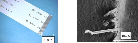
Left:Fig. 1. Photograph of FFC
Right:Fig. 2. Whisker formation observed on FFC at a connectors joint area
Left:Fig. 3. Results of AES analysis of tin-plating with zinc nano-coating
Right:Fig. 4. Results of XPS analysis of tin-plating with zinc nano-coating
Fig. 5. Model diagram of tin-plated surface samples with and without zinc nano-coating
| *1 | In a Vickers Hardness Test, a right-pyramid diamond indenter is pressed into a test material; after removal of the load, the two diagonals of the indentation left in the surface of the material are measured. |
| *2 | A mono-axial tensile test is performed by fixing one end of the test material and pulling horizontally in a single plane on the other end. |